
 Українська (Україна)
  Русский (Россия)
  English (United Kingdom)
 Today I'll describe a problem our client, a professional electrician, faced when he decided to install dynamic stairwell lighting. Given the length and power of the LED strips, we decided to use the Smart Stairway SS-26 LCD PRO V.4 controller. This was arguably the most challenging problem we've encountered in recent memory, requiring a significant amount of time to resolve due to a series of errors in cabling and equipment installation. The solution, however, turned out to be entirely different.
Description of the object and selected equipment.
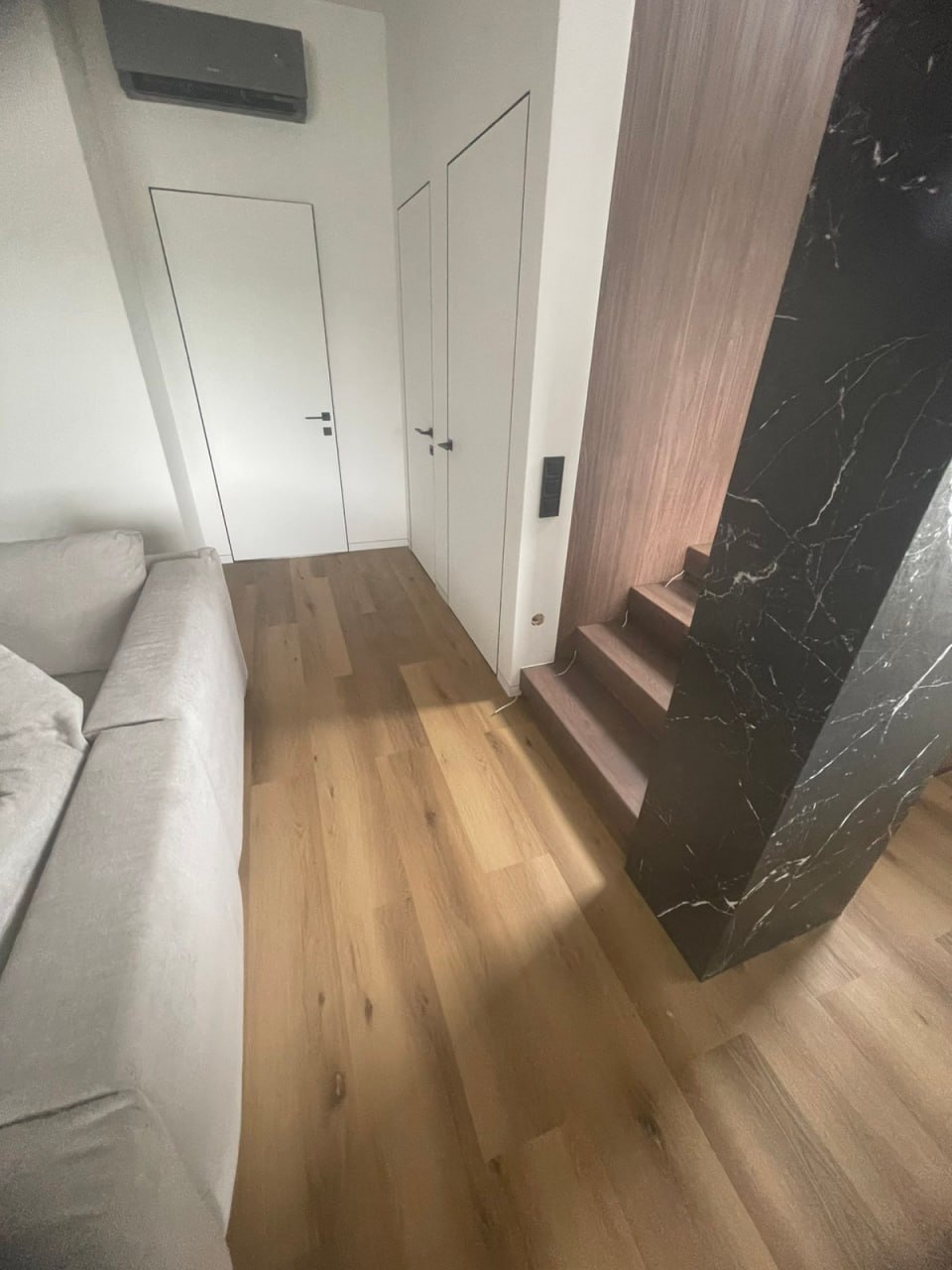
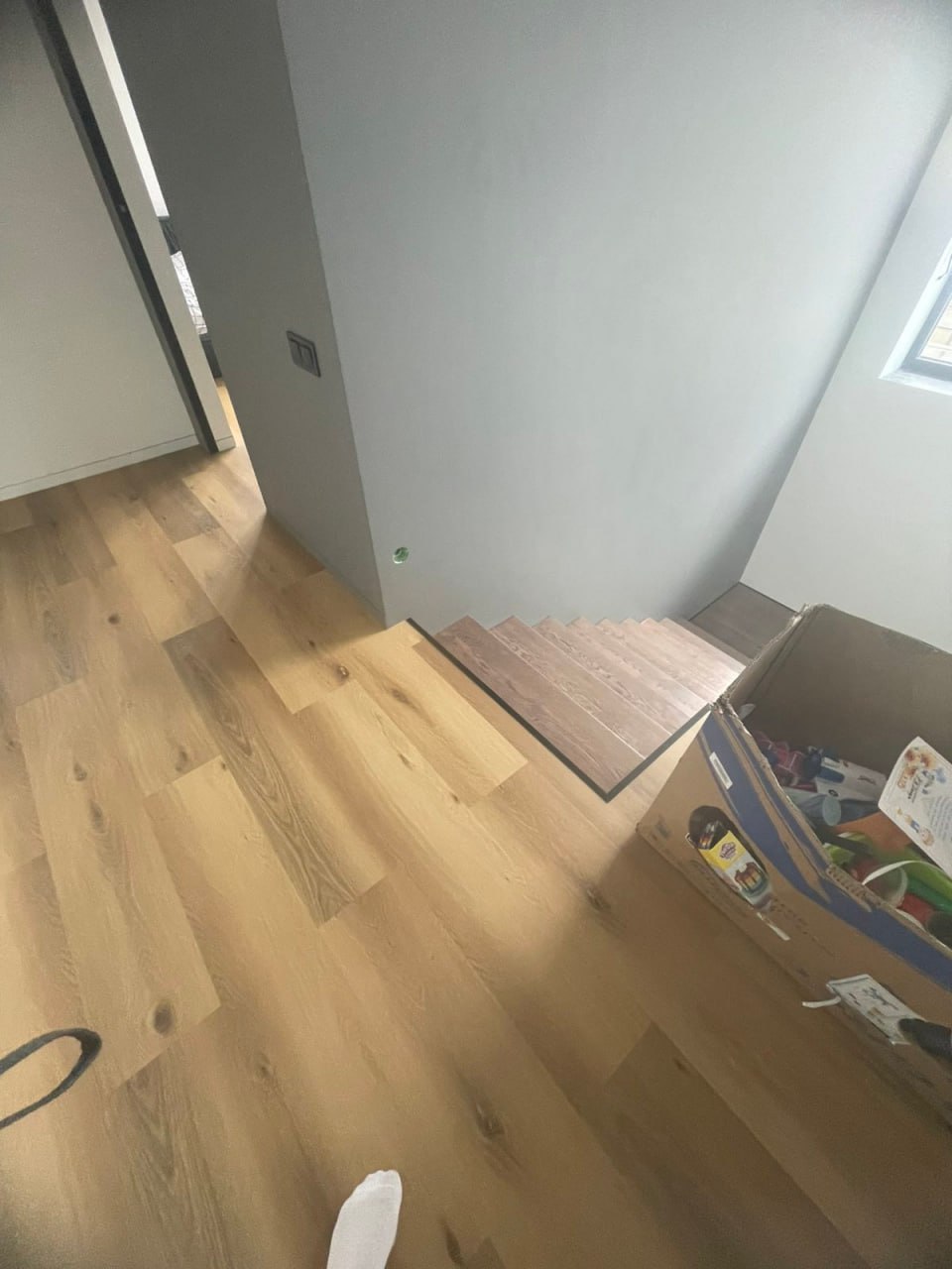
The staircase was already fully completed when the client contacted them. All finishing work had been completed, and the sensor installation sites had been prepared. Unshielded PVS 4x0.5 cables were installed to the sensors. The sensors faced traffic areas from above and below, so pyroelectric sensors were not an option, as they would trigger false alarms when passing by the staircase within their visibility range. Installing ultrasonic sensors was difficult because the cables were unshielded, and the sensor mounting height was too low. They could see the floor or steps and misread the distance. The use of IR rangefinders was also not recommended, as the staircase was 120 cm wide, and IR sensors were stable at distances of up to 80 cm. It was decided to offer the client ultrasonic sensors, but tilt them upward by 10 degrees.
The essence of the problem:
After connecting, the customer reported constant activation from the bottom sensor, which could indicate either the sensor is receiving a reflected signal from the floor or interference in the unshielded wire. A video demonstrating the distances measured on the display showed that the distance fluctuated between 120 cm and 5 cm in random mode, and the second sensor was not receiving a signal at all.
We asked the client to connect the sensors directly to the controller and observe the results. The video shows both sensors operating in this mode, but the values vary significantly. However, we don't know where the person with the camera is standing relative to the sensors or whether there are any other obstacles in front of them.
To eliminate potential wiring issues, we decided to replace the sensors with IR rangefinders. IR rangefinders maintain a high signal in the signal wire in standby mode and only when triggered do they pull up to zero and send a low signal to the controller input, initiating the backlight. This is important if the signal wire is unshielded and runs near LED strip power wires. This can result in inductive interference in the wire, making it impossible to use pyroelectric or ultrasonic sensors. Replacing the sensors resolved the random activation issue and enabled the project to be handed over to the client. However, a couple of days later, the client contacted us again with a problem: the RCD was tripping when the stairwell backlight was turned on using the pushbutton switch. This raised a lot of questions for us, as the pushbutton is connected to the controller's 5V output, while the RCD is on the 220V AC power line. Obviously, this is theoretically impossible.
Upon arrival at the staircase installation site, our client discovered that the controller wasn't working at all. We asked for a replacement controller and discovered that everything was working as expected, except that the additional "-" power terminal had been mechanically torn out, and three strands of the PVS 3x1.5 cable had been twisted and directly soldered through a hole in the housing to the controller board where the screw terminal had been torn out.
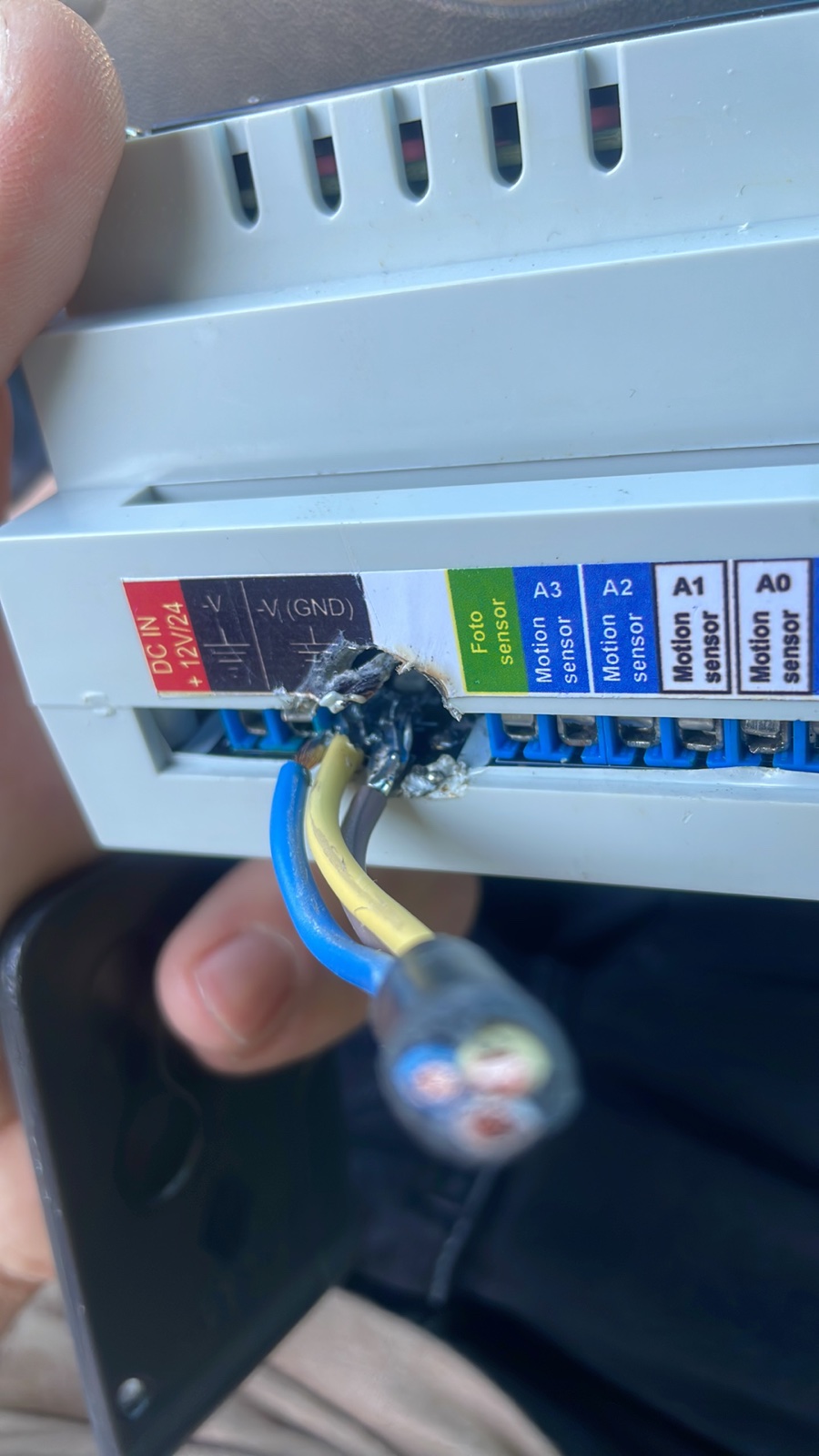
Because the soldering was done carelessly, touching the wire shorted it to the "+" terminal, which could cause a short circuit and trip the power supply. We replaced the broken terminal, tested the controller for 24 hours on our test bench with trip logging, and sent it back without finding any issues. The customer installed the controller and it worked fine for a few hours, but the same thing happened again that night. Upon arrival, we discovered that after powering on, the controller was displaying artifacts and freezing.
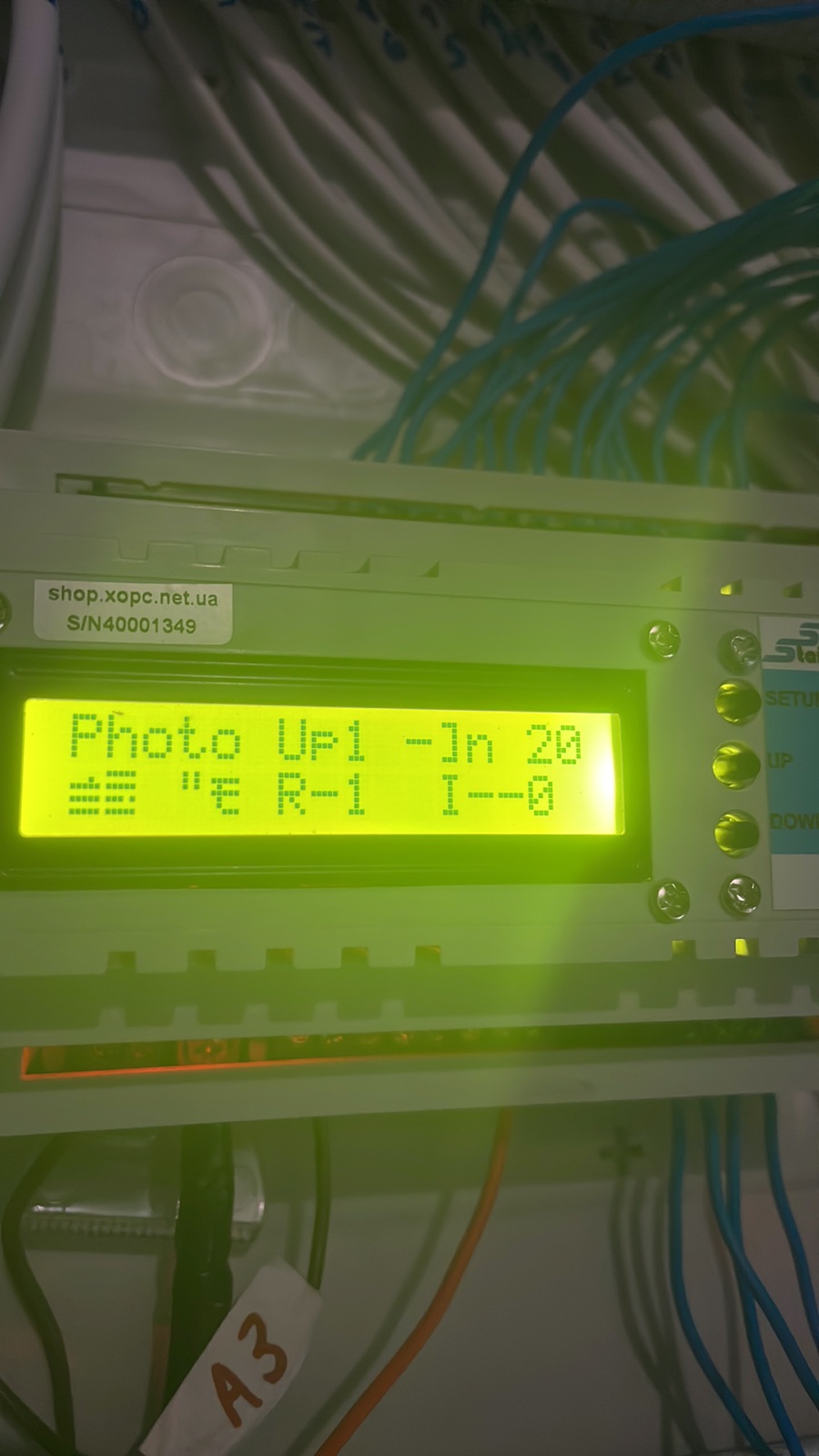
The RCD tripping when pressing the power button connected to the +5V output of the controller suggested poor insulation of the wire and that the nearby 220V AC wire in the outlet was also damaged and shorting through the plaster, triggering the RCD and causing a breakdown on the wire from the 5V button. This triggered the self-resetting 0.5A, 6V PTC fuse in the controller, installed after the DC5V power stabilizer in the controller circuit. We were asked to measure the resistance of the sensor wires. Although the resistance was twice as high as expected, this could be due to either a measurement error or the wire material being bimetal rather than copper. Everything was generally normal. A solution was adopted to remove the PTC fuse from the microprocessor and install an additional 0.75A, 5V fuse on the peripheral power output (sensors and buttons). This should prevent a complete controller shutdown in the event of problems with the wires leading to the sensors and/or buttons. In this case, only the 5V peripheral power supply would be disconnected, but the controller would continue to operate. One question remained: why were the client's display artifacts and gibberish? This could indicate that the problems were caused by power supply sags or interference. So, in addition to the quality of the wiring, we had another concern: the power supply. Since the client didn't have an oscilloscope or even an accurate multimeter to check the power supply, we replaced the DC/DC Step-Down 5V power supply circuit, adding a ferrite filter and additional filters based on 1000μF electrolytic capacitors at the input and 470μF at the output. The new voltage converter is built on a microcircuit that is not susceptible to heat, so the additional issue of the controller's protective shutdown due to overheating was also eliminated, as there is no thermal protection. After testing the old controller sent by the client and the new one customized for their project on our test bench with error logging for four days, we found no errors. After developing a plan to troubleshoot the problem, we sent a new controller to the customer.
Troubleshooting plan.
- Controller installation - observation
- Replacing the power supply - observation
- Replacing wires to sensors - observation.
After installing a new controller, the client reported that the controller was working, but the lower sensor was constantly sending a signal to turn on. Obviously, for the selected IR sensor type, this means a logic zero at the controller input and in the signal wire. This means either the sensor is already damaged or there's an open circuit. Since the sensor test showed it was working properly when directly connected to the controller, the client concluded that the wire was damaged somewhere. The decision was made to replace the wires. And then came the most interesting part. Since the wires were installed in a corrugated sleeve under the drywall walls and couldn't be pulled out, the client decided to remove the drywall panel and received an electric shock when he touched the drywall profile. After removing the panel, everything became clear. See the photo below.
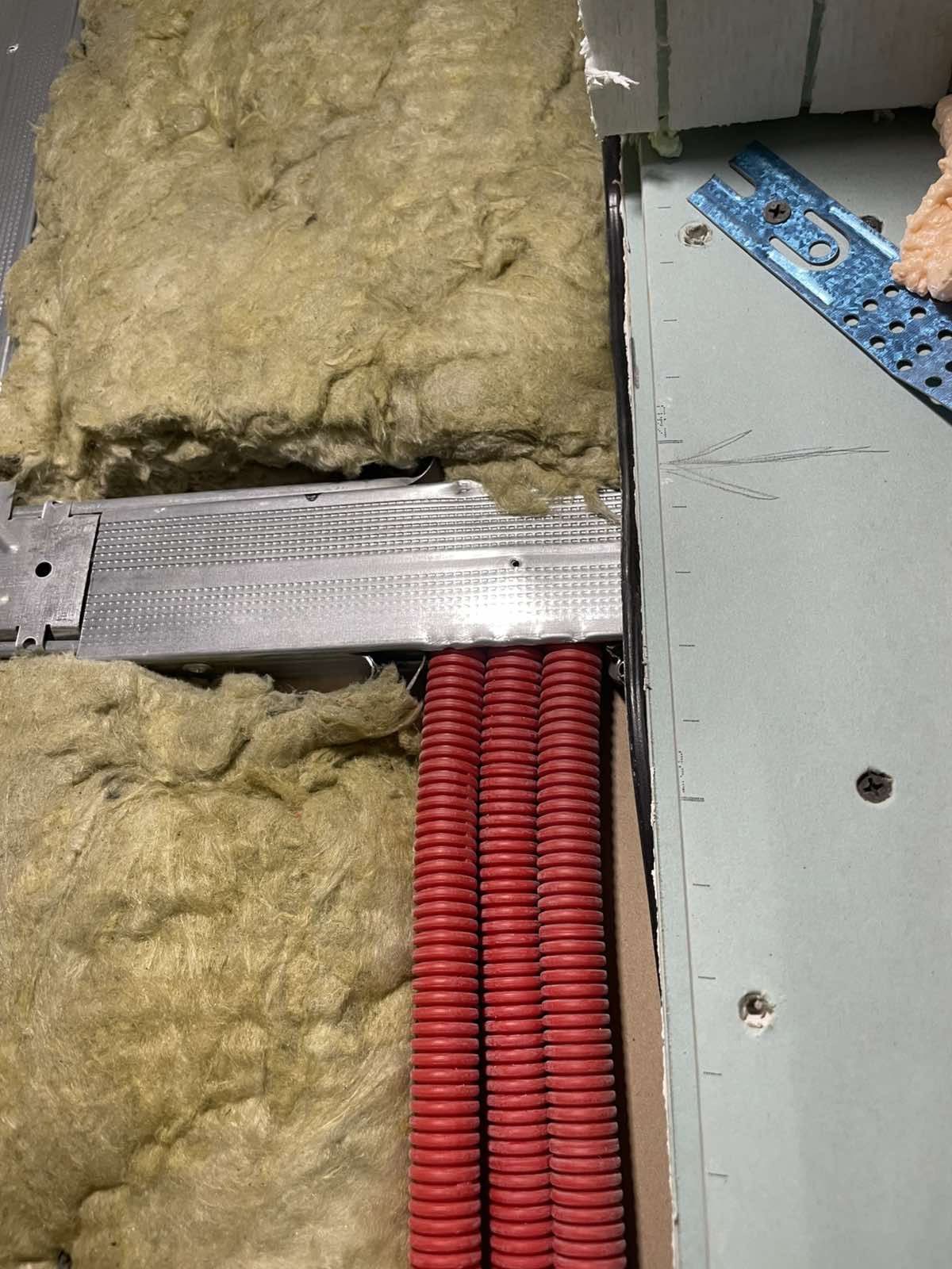
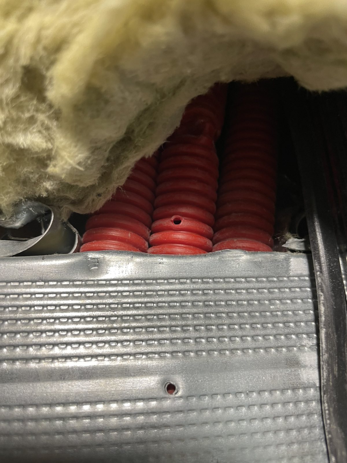
During the drywall installation, the builders drove screws through the corrugated conduit, piercing the high-voltage cable and signal wires. Only because they used a SmartStairway SS-26 LCD PRO V4 controller, equipped with input surge protection, did the controller burn out. Replacing the wire solved all the problems. Unfortunately, we don't know which wire was damaged or when high voltage was applied to the controller input. Whether it was a wire from a specific switch, with the phase only being applied when the light was turned on, or a common phase—we don't know, as our client chose not to delve into the work for which they weren't responsible and only replaced some of the wires. The drywall metal structure still showed 127V. It also became clear that, although the controller withstood the high voltage applied to its digital inputs, the power supply was still damaged, apparently causing the controller to periodically freeze and display glitches. We didn't receive the power supply, so we weren't able to check its voltage and ripple levels, but we're 99% sure that was the problem, as replacing the power supply resolved the freezing issue. The mere fact of such a careless approach to work simply shocked us. We offer our sincere sympathies to our client, who was working on dynamic lighting for the first time and was faced with such negligence from the drywall "specialists" from the very start. We're truly glad that all the equipment remained intact and no electricians were injured. :) The problem has been resolved.