
 Українська (Україна)
  Русский (Россия)
  English (United Kingdom)
Automatic ARGB staircase lighting with addressable smart strips.
In this section, we will consider the features and methods of creating LED lighting for stairs using addressable ARGB color LED strips. Consider the pros and cons of this backlight option, the operating principle and the intricacies of choosing addressable LED strips, select equipment and consider installation and connection methods.
What is an ARGB addressable LED and how is it arranged.
An addressable LED is a regular RGB LED, the colors of which are controlled by a special microcircuit that controls its colors and the brightness of each color channel. In fact, you can control the color and brightness of each individual LED or segment of several LEDs, which depends on the type of microcircuit used. The essence of controlling such strips is that a certain set of bits is transmitted for each color channel. Control is based on serial data transmission — each LED receives a bit stream, "takes" the first 24 bits (its own) and sends the rest further.
Data format for one LED:
-
24 bits = 8 bits green + 8 bits red + 8 bits blue
-
Byte order is usually GRB
A single-wire asynchronous protocol with fixed timing is used:
-
One bit is encoded by the pulse width.
-
Transmission frequency is ≈ 800 kHz (period ~1.25 µs per bit).
As can be seen from the operating principle of these LED strips, the number of control chips (WS2811, WS812 LED drivers or their analogs) is important. For example, if you plan to use 300 pixels, the packet length will be 300 * 24 = 7200 bits. Each frame change implies sending a new packet. Therefore, not all microcontrollers can implement this for a large number of pixels, since they may not have sufficient speed and memory. Also, as we can see from the characteristics of the data transfer protocol, the frequency is 800 kHz, which places high demands on the length of the transmission channel and the quality of the wire. And if each chip is a level amplifier when transmitting a packet to the next chip, equalizing the signal level to the segment supply voltage, then with the transmission line everything is more complicated and for connecting more than 30 cm, at least a twisted pair is required, where the data wire is twisted with the "GND" wire, and if the length is more than 1 m, then a coaxial wire must be used, but in any case, you need to strive to install the controller as close as possible to the connection point and minimize the length of the wire. The second important parameter follows from the fact that each chip acts as a logic level converter, so the quality of the power supply is important for it, which makes these types of tapes demanding on the quality and level of pulsations of the power source. Therefore, with a low-quality power source, you will receive a large number of corrupted data packets, which will appear on the tape as chaotic blinking of the entire tape or individual LEDs with various unexpected colors and brightness.
The main and unconditional advantage of addressable LED backlighting is the flexibility of color and dynamic solutions, allowingadjust the color, dynamics, number of LEDs for each step, if your staircase is of a complex shape with steps of different lengths. The main disadvantages are the high price of LED strips, the demanding quality of wiring and power supply, the requirements for careful and correct installation, the need for basic knowledge and skills in the work. But if you are ready to try yourself, then the result is worth it.
Today, there are two most widely represented types of ARGB LED strips on the market:
- built on the WS2811 control chip and their various Chinese analogues
- built on the WS2812 chip and their various Chinese analogues
WS2811
LED strips of this type usually have a supply voltage of 12 or 24 V DC. Each segment of such an LED strip has one WS2811 chip and three series-connected RGB SMD5050 LEDs, a capacitor and 3 ballast resistors for each color. Or for 24V strips, these are 6 LEDs connected in series in each segment, respectively. As can be seen from the diagram, one WS2811 chip controls all the LEDs of a segment simultaneously. Therefore, a segment can be considered one color pixel or dot. COB LED strips, which are gaining popularity now, also work, where 1 chip can have dozens of small LEDs that create a monolithic light fill. As a rule, COB strips are built on the basis of WS2811 chips
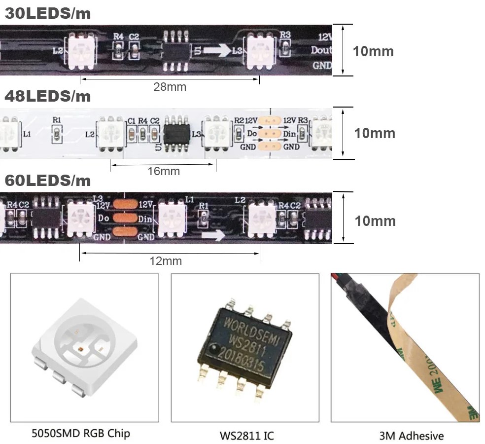
As a rule, such LED strips have the following power:
- DC 12V, WS2811, 30 LED/M, - 7.2W/m (0.6 A/m)
- DC 12V, WS2811, 60 LED/M, - 14.4 W/m (1.2 A/m)
- DC 12V, WS2811, 48 LED/M, - 11.5W/m (1 A/m)
- DC 24V, WS2811, 30 LED/M, - 7.2W/m (0.3 A/m)
- DC 24V, WS2811, 60 LED/M, - 14.4 W/m (0.6 A/m)
- DC 24V, WS2811, 48 LED/M, - 11.5 W/m (0.5 A/m)
WS2812
This type of LED strip is built on the basis of a WS2812 microchip, which is built directly into the housing of the SMD5050 RGB LED.
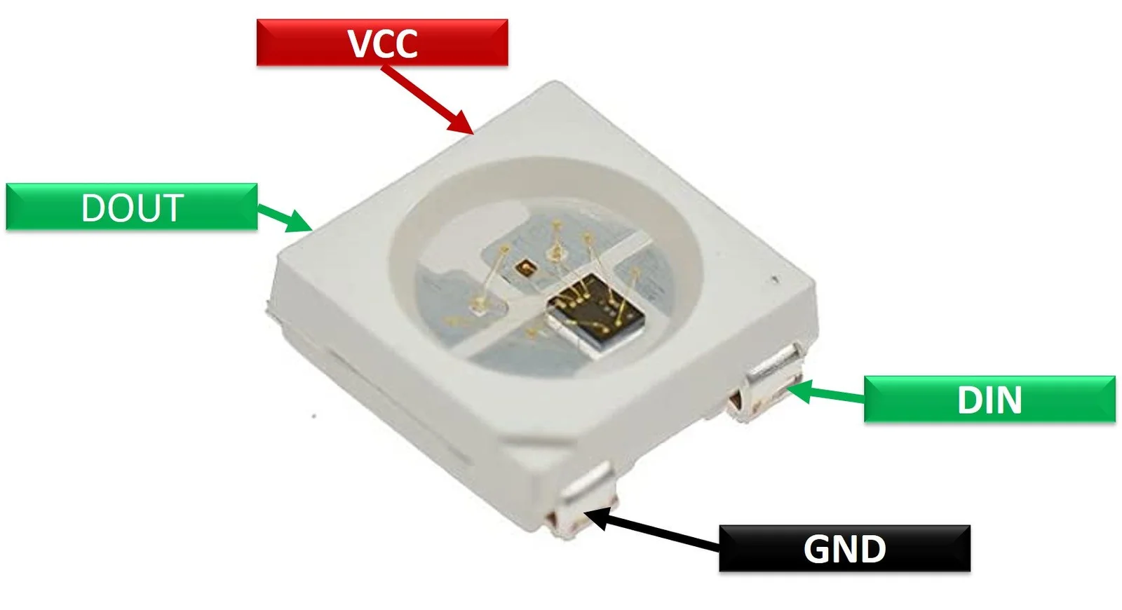
One segment or pixel of such a LED strip has one LED and each individual LED can be controlled individually. Street advertising monitors are built on the basis of such LEDs, they allow you to create stunning effects and animation. But since the LED can still only be powered by 5V, it entails special restrictions on current strength and the choice of wire cross-section area, as described in the first and second parts.
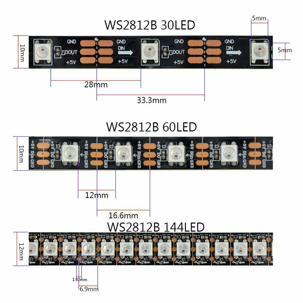
Choosing a strip and calculating the cross-sectional area of wires.
Characteristics of the RGB WS281x LED
| Color | Wavelength (nm) | Luminous intensity (mcd) | Current (mA) | Supply voltage (V) |
| Red | 620-630 | 550-700 | 20 | 1.8-2.2 |
| Green | 515-530 | 1100-1400 | 20 | 3.0-3.2 |
| Blue | 465-475 | 200-400 | 20 | 3.2-3.4 |
As can be seen from the table, 1 LED WS2812 consumes 60mA of current in maximum white brightness mode. The supply voltage of the WS2812 LED is always 5V (requires strictly 5V ± ~0.2V).
Then it is not difficult to calculate the current for the LED strip:
-
60 LED/m: up to 3.6A/m (maximum).
-
30 LED/m: up to 1.8A/m.
-
144 LED/m: up to 8.6A/m (!).
Pay special attention to this. For example, if you have 17 steps of 1 meter each, you will need 17 meters of tape. And the total current for 17 meters will be:
-
60 LED/m: up to 3.6A/m (maximum). - 61.2A (Power supply without taking into account the power reserve DC5V, 350W)
-
30 LED/m: up to 1.8A/m. - 30.6A (Power supply without power reserve DC5V, 153W)
-
144 LED/m: up to 8.6A/m (!). - 146.2A (Power supply without power reserve DC5V, 731W)
And the main problem here is the cross-sectional area of the wires. Use the calculator below to calculate the cross-sectional area of the wires.
Copper Wire Cross-Sectional Area Calculator
ρ (copper) = 0.0175 Ohm mm²/m
As you can see, given that you will have to lay the power bus in parallel with all the steps, the length of the wire will probably be at least 10 m.
Then for WS2812 tapes of different densities in the example under consideration for 17 meters of tape you will need wires with cross-section:
-
60 LED/m: up to 3.6A/m (maximum). - 61.2A (Power supply without taking into account the power reserve DC5V, 350W), cable cross-section not less than: 87 mm2
-
30 LED/m: up to 1.8A/m. - 30.6A (Power supply without power reserve DC5V, 153W), wire cross-section not less than: 44 mm2
-
144 LED/m: up to 8.6A/m (!). - 146.2A (Power supply without power reserve DC5V, 731W), wire cross-section not less than: 205 mm2
Which is basically an impossible task. Therefore, it is obvious that WS2812 LED strips are not suitable for stair step lighting if we are talking about lighting each step along its length and a large amount of strip with long wires is required. But on the other hand, this type of strip can be suitable for stair lighting when installing the strip parallel to it in a groove on the wall or along the railing. We will consider this method of stair lighting separately in Part 4.
For comparison, if you use the WS2811 LED strip, for the same project with 17 steps of 1 meter each, and a wire length of 10 m, you will need wires:
- DC 12V, WS2811, 30 LED/M, 7.2W/m (0.6 A/m) - 10.2 A, 122.4 W, wire 6 mm2
- DC 12V, WS2811, 60 LED/M, 14.4W/m (1.2 A/m) - 20.4 A, 245 W, wire 12 mm2
- DC 12V, WS2811, 48 LED/M, 11.5W/m (1 A/m) - 17A, 204 W, 10 mm wire2
- DC 24V, WS2811, 30 LED/M, 7.2W/m (0.3 A/m) - 5.1 A, 122.4 W, 1.5 mm wire2
- DC 24V, WS2811, 60 LED/M, 14.4 W/m (0.6 A/m) - 10.2 A, 245 W, 3 mm wire2
- DC 24V, WS2811, 48 LED/M, 11.5W/m (0.5 A/m) - 8.5A, 204W, 2.5mm2
Of course, all calculations are made for the maximum possible current consumption in static white mode at maximum brightness. In practice, you will most likely use color variations using dynamic modes and lower brightness, but the choice of wiring for the power bus is very important not only for the high-quality operation of the project, but also for your safety, since wires with insufficient gauge can heat up a lot, which can cause insulation melting, short circuit and fire. This will also lead to significantvoltage drop at the end of the wire, as a result of which the color of the LEDs at the end of the strip will differ from the color at the beginning, or the entire strip will not work. Choose the wire responsibly.
Use a coaxial cable as a data cable, connect the central core on one side to the output of the controller's information channel, and on the other side to the DIN contact of the LED strip. Do not forget that addressable LED strips have a direction, each segment has an input, usually designated Din (DI) and an output designated DOut (DO). The output of the previous strip is always connected to the input of the next one.
Selection of power supply, installation location and type of sensors.
The calculation of the power supply, as described in the previous parts, is carried out based on the total power of the entire length of the LED strip plus a power reserve of at least 20%, after which a power supply of the corresponding voltage to the strip with the calculated power from the closest available rating in the assortment is selected. The choice of the installation location of the sensor and its type was also described in detail earlier and is no different for stairs using an addressable LED strip.
Choosing a controller to control an addressable LED strip installed on a staircase.
Our company has developed and offers you a compact controller for lighting stairs with an addressable LED strip. This is a controller SmartStairway SS-281x Wi-Fi. The controller has a built-in Wi-Fi module, it can create its own access point to connect to its built-in WEB server for settings. or it can automatically connect to the home network automatically using a static address or DHCP. By connecting to the controller's WEB server, you can set the required number of steps, the number of pixels for each of the steps, the effect of switching on, color, brightness, speed. Also the effect of standby mode (when there are no people on the stairs), color, brightness, dynamics. The controller allows you to use the adaptive brightness mode, when depending on the brightness in the room, the brightness of the LEDs will decrease so as not to cause blinding, you set the maximum and minimum thresholds of adaptive brightness to your own taste, read more on the product page and watch the video below.
Installing LED strip on stairs.
Before installing LED strips, it is necessary to prepare the places for installing the strip. If you install the strips under the step in the groove, it is very convenient to use aluminum profiles with a matte milky white diffuser. Before gluing LED strips into the profile, the profile surface should be degreased and preferably painted or glued with insulating material, since the LED strips have soldering points on the back side and a thin layer of double-sided layer, which is easily damaged when gluing the strip into the profile or when heated during operation, which can cause a short circuit of the LED strips on the metal surface of the profile and thereby cause damage to the equipment and the LED strips themselves. Pay close attention to this point. Be sure to insulate the ends of the LED strips on the side where the wires are soldered and on the opposite side with heat-shrinkable tube. This is necessary in order to exclude a short circuit on the metal surface of the aluminum profile of the soldering points and the cut of the LED strip. Be sure to thoroughly wash the soldering points from the flux (even rosin) before insulation, since any flux (except for some no-clean ones) eventually becomes saturated with atmospheric moisture, corrodes and causes short circuits and destruction of the solder.
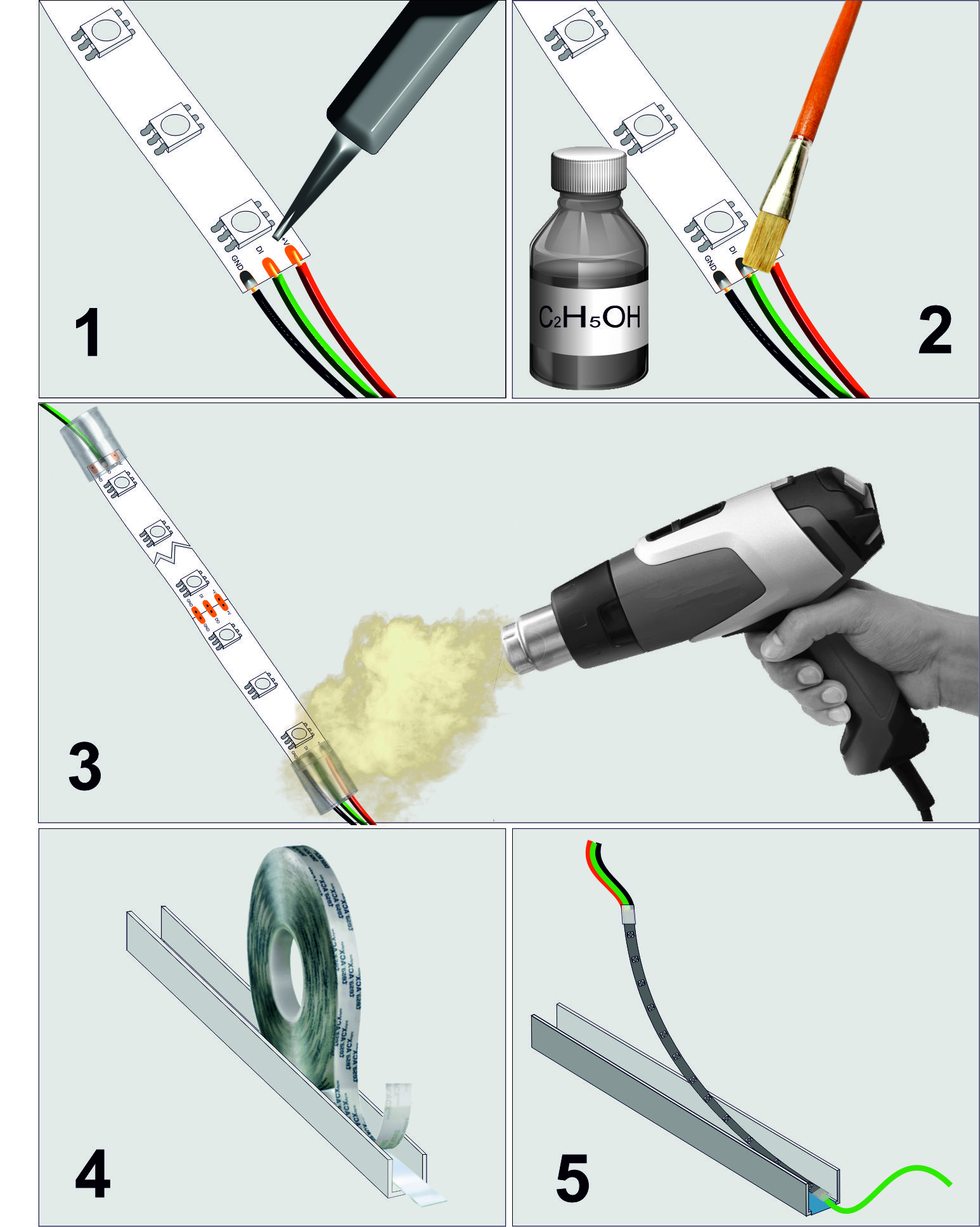
The procedure for installing LED strips in a metal profile for LED strips.
- Solder the wires to the LED strip. 2. Wash off the flux with alcohol or cleaning liquid. 3. Insulate the ends of the LED strip with heat-shrinkable tubing. 4. Degrease the inner surface of the aluminum profileand glue with insulating tape. 5. Glue the LED strip into the profile.
Next, you should lay the power bus from the first to the last step, since the current with this version of stair lighting can be quite high, adhere to the calculated values of the cross-sectional area of the wires according to our calculations above. Connect the LED strips of each step to the power buses, observing the polarity. Then lay the information channel for the LED strips, try to ensure the minimum length of these wires, do not lay them near the power wires, use a coaxial wire. Do not forget that addressable LED strips have a direction, i.e. DI input and DO output. Be especially careful not to short-circuit the connection points with power wires, as this will damage the entire LED strip, because addressable LEDs are very demanding on the supply voltage and connecting 5V LEDs to a 12 or 24V line will certainly destroy them all and may damage the controller. The diagram for installing equipment on the stairs is shown in the diagram below.
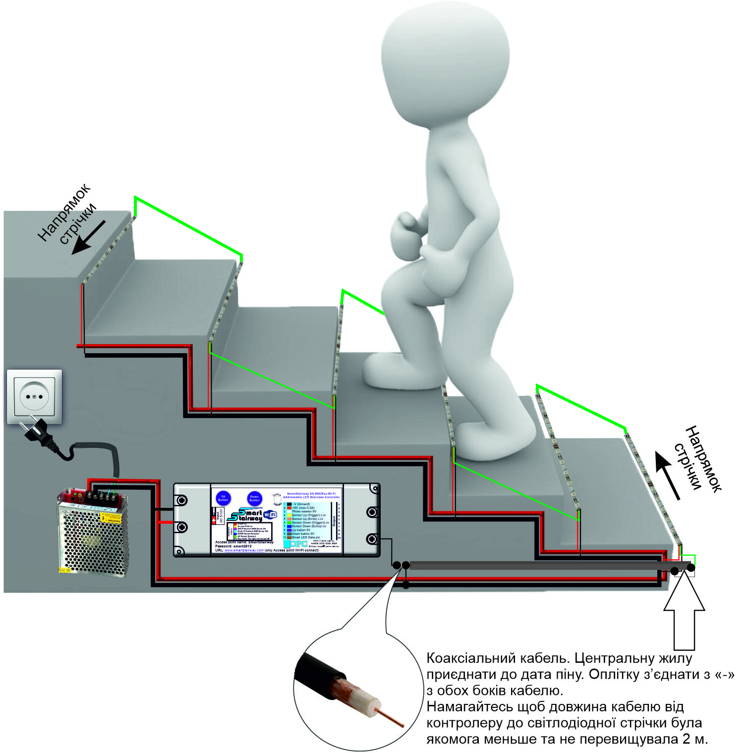
Configuration and commissioning.
After all the equipment has been installed, we strongly recommend that you use a multimeter to ring all soldering and connection points, make sure that there are no short circuits or breaks and that everything is connected correctly. If errors are detected, fix them. After this, you can turn on the system power and proceed to configuration. When turned on for the first time, the controller will switch to the access point mode after switching on. You can connect to it via Wi-Fi You can connect to it using your smartphone or PC. As a rule, the controller will have an IP address of 192.168.1.4 or a web address of www.smartstairway.com, the transition to the web address is possible only if your smartphone or PC is not connected to other networks and does not have access to the Internet. On the WEB-page of the controller settings, you need to select the type of LED strip you are using, specify what type of sensors you are using, if ultrasonic sensors are used, specify the response distance. Specify the number of steps and the number of pixels for each of them. Save the settings and restart the controller by turning the power off and on. The remaining settings can be made later, since these settings are already enough to check and start the system. Detailed connection, setup and much more are described in detail on the product page and in the user manual, available for download on the product page. If during the setup process you specified a connection to a local network or router, then after turning on the power the controller will automatically try to connect to the router, if the connection fails, after several attempts it will switch to the access point mode. It is important to understand this so that if you decide to set the IP addresses of your network manually, instead of using DHCP, a situation may occur when the controller successfully connects to the router, passes the password check, but you will not be able to connect to the controller due to an incorrectly specified IP or network mask. In this case, you just need to turn off the router so that the controller cannot connect to it. Turn on the controller and wait until it switches to access point mode, then connect to it from your smartphone or PC and correct the error you made.