
 Українська (Україна)
  Русский (Россия)
  English (United Kingdom)
 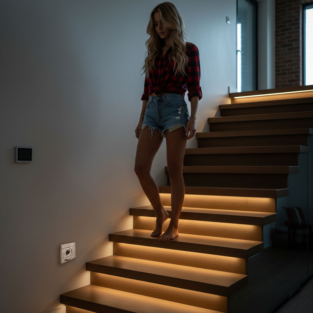 As our many years of practice have shown, a fairly common problem when creating automatic stairway lighting is the lack of wires for connecting sensors and/or activation buttons. Also, wires are often chosen or laid incorrectly, which complicates their use and can lead to false triggering of the lighting due to induction interference. Quite often, this is discovered only after all finishing work is completed. However, this is no reason to abandon the project. Especially for such cases, we have developed wireless sensors and buttons with EV1527 coded radio channels, supporting up to 12 devices and 4 channels. This means you can use up to 12 sensors, buttons, or remotes, placing them in the most optimal locations.
Wireless sensors and buttons operate at 433 MHz and use the popular EV1527 coding protocol. To connect these devices to the SmartStairway SS automatic staircase lighting controller, you will need a 4-channel receiver: Smart Stairway RFM-Ev1527-4. Please note that the receiver usually comes with the sensors and buttons you order from us already paired. However, you can program the receiver yourself. Below, we will explain how to do this.
First, let's look at the specific sensors and buttons we offer.
Pyroelectric Sensors (PIR)
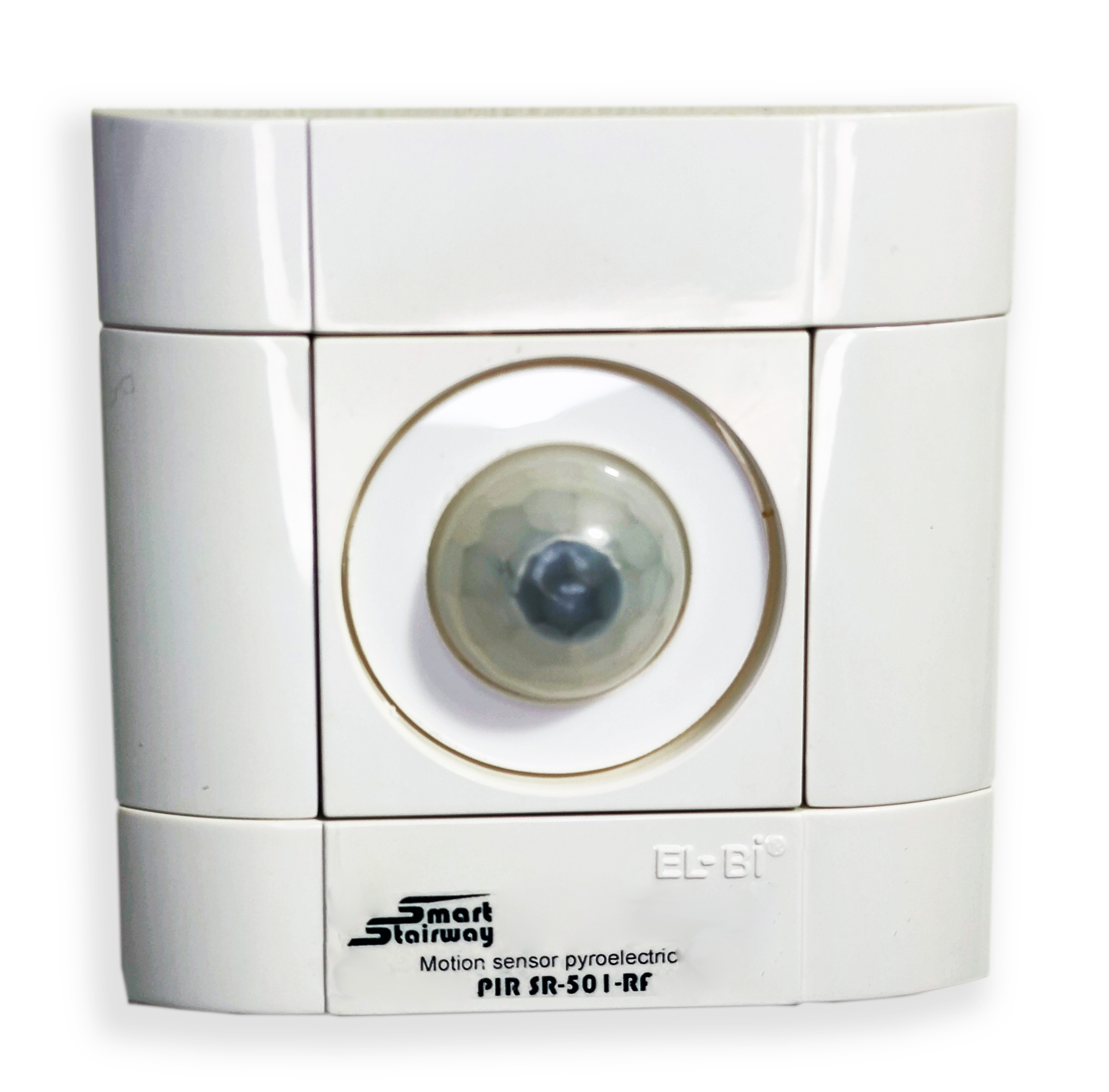 This model is an improved version of the popular Smart Stairway PIR-SR501-1 pyroelectric sensor, which we have been producing for over 10 years. We have added a wireless communication protocol while maintaining the same housing and design. The sensor performs single measurements with a 3.5-second delay and has a detection angle of less than 45 degrees. This distinguishes it favorably from other solutions, such as Aqara sensors, which detect motion within a 130-degree radius and have a 60-second delay. This means you won't have to wait a minute to reactivate the light after it triggers, and the sensor won't react to movement far beyond the stairs.
Sensors are physically pre-configured to one of two channels: "A" or "B". Accordingly, the receiver will perceive the sensor signal as a trigger for the corresponding channel. Keep this in mind when purchasing. The sensor can be powered in a wide range from 4.5V to 19V. Therefore, you can power it from a 9V "PP3" battery or from 4 series-connected AA or AAA batteries.
| Power Source | Capacity | Lifespan (Theor.) | Lifespan (Real*) |
| 9V Battery (PP3) | 500 mAh | ~130 days | ~3-4 months |
| 3 x AA (LR6) | 2000 mAh | ~530 days | ~1 year |
| 2 x Li-ion 18650 | 2500 mAh | ~660 days | ~1.5 years |
It is also possible to take power from the LED strip of the top or bottom steps, which is more practical as it eliminates the need for battery replacement. This type of sensor is recommended to be installed directly above the step surface. Note that this is only relevant when using LED strips with a supply voltage of no more than 12V. For 24V strips, we can manufacture sensors with appropriate support upon request. Please contact us for details.
| Parameter | Value |
|---|---|
| Dimensions | Max. 80x80x45 mm, recessed 60x40x30 (WxHxD) mm. |
| Supply Voltage | DC 4.5V – 20V |
| Current Consumption | 22 µA / trigger |
| Radio Frequency | 433 MHz, EV1527 coding, Channel "A" or "B" |
| Detection Distance | 0.3 – 7 m |
| Detection Angle | Up to 45° |
| Pulse Duration on Detection | 3.5 sec. |
| Blocking Time Before Next Measurement | 2.5 sec. |
| Operating Temperature | 0 — +80°C |
| Operation Mode | L – Single trigger |
| Average Distance from Receiver, m | 30m indoors, up to 100m in open space. |
Please note that the reliable range depends on the material and number of walls. Do not use metal mounting boxes, as the radio module antenna is located on the back of the device.
Wireless Switch. Momentary Button.
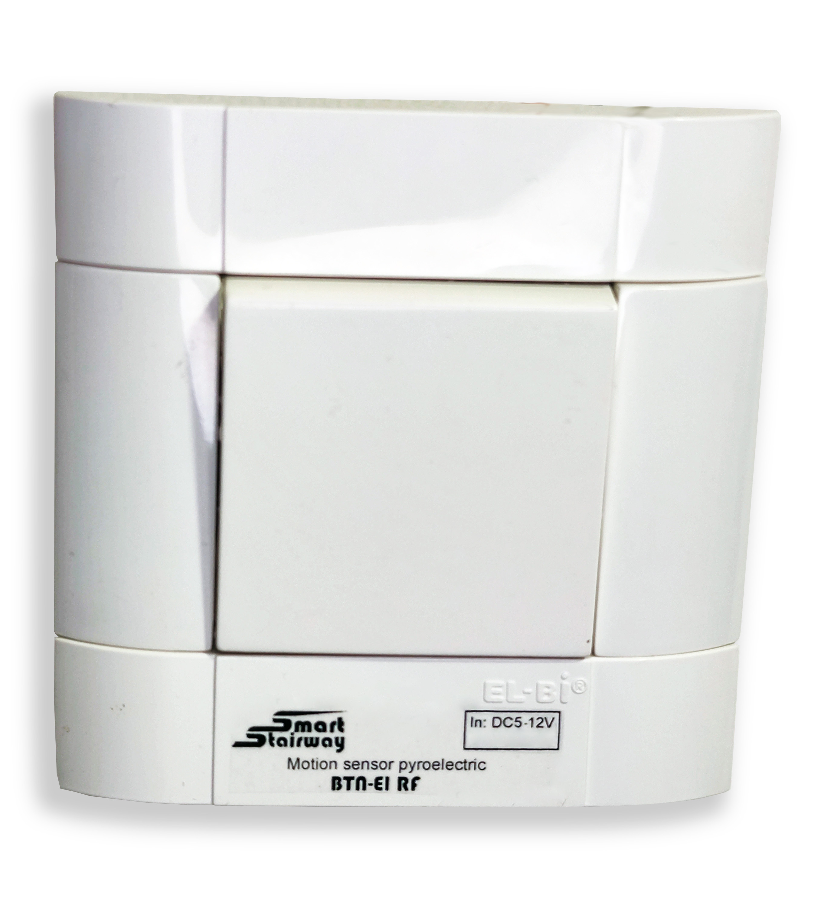 If you want to equip your stairs with manual override buttons, you will need devices for the upper and lower stair zones. Our SmartStairway SS series controllers have a manual override function: the light activates when one of the two buttons is pressed and stays on until either of them is pressed again. Lighting activation occurs in the direction from the pressed button (top or bottom), and deactivation happens in reverse order. For wired buttons, you need to connect the +5V output of the controller to the button and the second wire to the corresponding input. If wires are not provided, you can use Smart Stairway BTN-EL RF wireless buttons. The button can be powered by 3.3 – 24V, meaning both from batteries or from the LED strip of the nearest step. Battery lifespan is indicated in the table below:
| Power Source | Capacity | Lifespan (Theor.) | Lifespan (Real*) |
| 9V Battery (PP3) | 500 mAh | ~130 days | ~3-4 months |
| 3 x AA (LR6) | 2000 mAh | ~530 days | ~1 year |
| 2 x Li-ion 18650 | 2500 mAh | ~660 days | ~1.5 years |
Button Transmitter Technical Specifications:
- Data Transmission Power: 11 dBm.
- Operating Voltage: 3.3 – 24V.
- Operating Frequency: 433 MHz.
- Range: Up to 100 m.
- Current Consumption (Transmitting): 10 mA.
- Current Consumption (Standby): Less than 3 µA.
- Signal Coding: EV1527 Learning code.
Below is a typical recommended connection diagram for buttons, sensors, and the receiver to SmartStairway SS-26, SS-26 LCD, SS-26 LCD Pro, and SS-281x Wi-Fi controllers.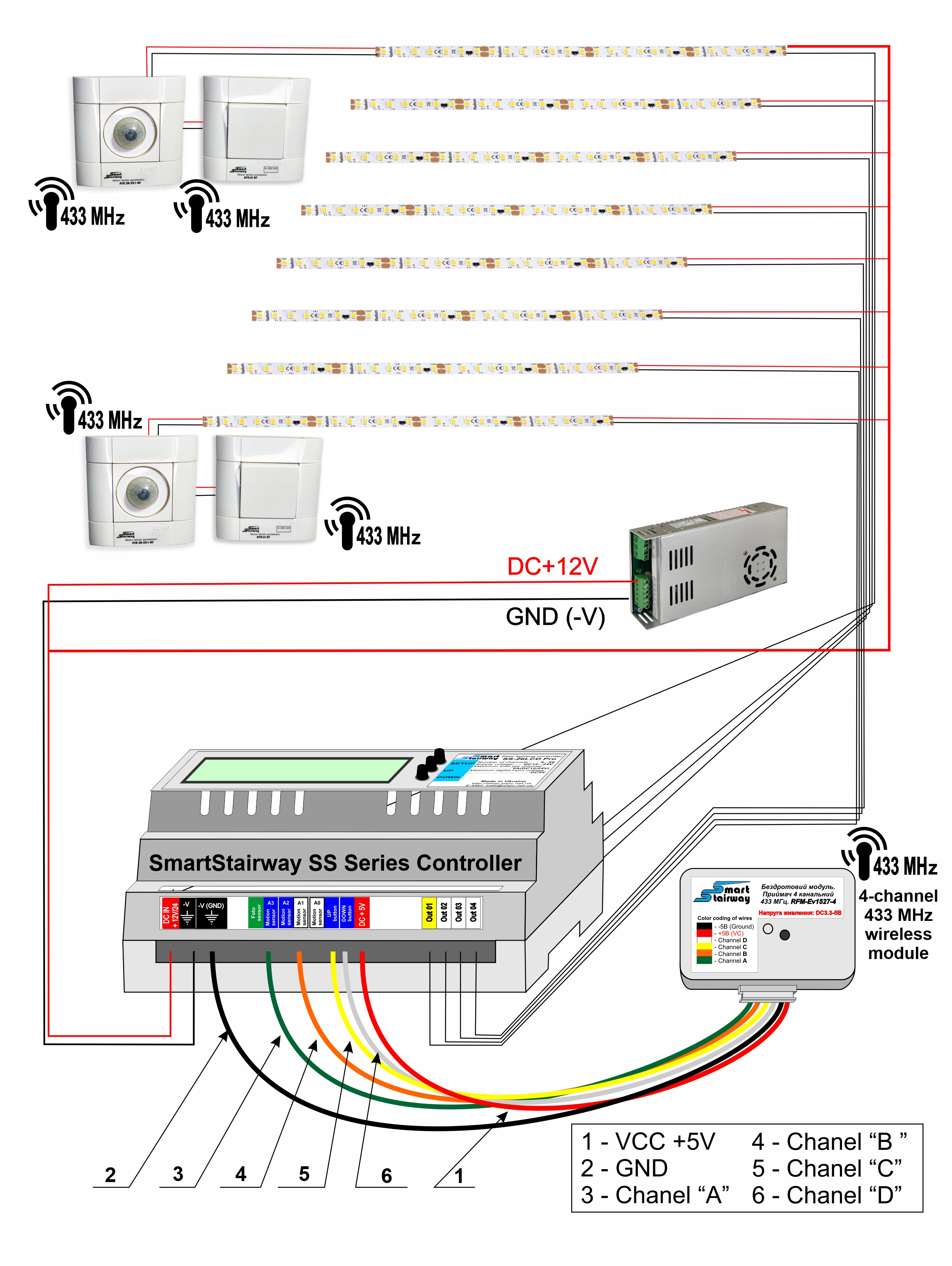
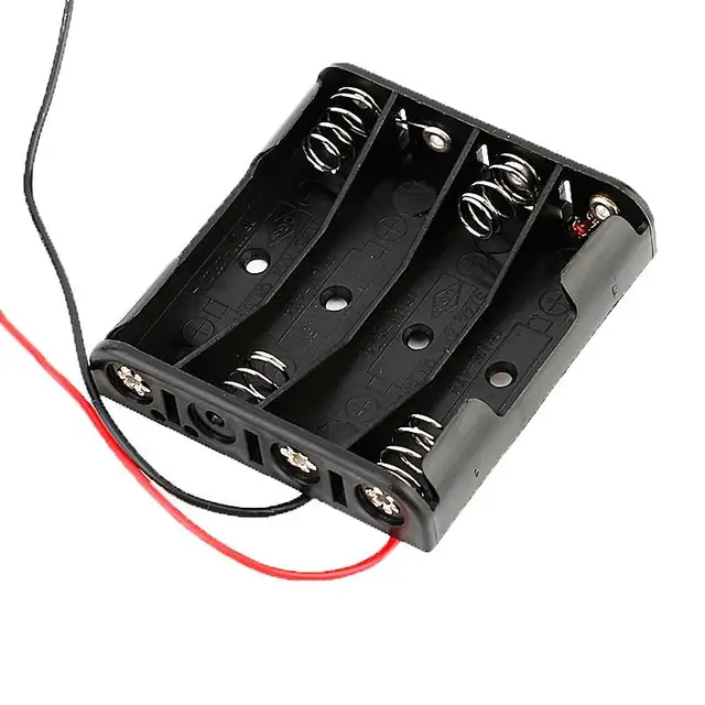
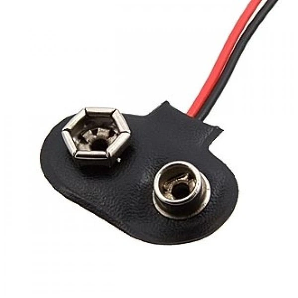
If you wish to use batteries or accumulators for power, you will additionally need power cells and a battery box. Note that for sensors, it is recommended to use a voltage of at least 4.5V, while buttons can work from 3.3V. Therefore, for sensors, it's better to use at least 4 series-connected AA batteries, whereas three are sufficient for buttons. You can also use a single 9V battery. For connecting AA or AAA batteries, we recommend using the battery compartment shown in the photo or a 9V battery clip.
Also, don't forget that switches (buttons) have physical channels "C" or "D". The receiver will trigger the corresponding channel. Keep this in mind when ordering this product on the website.
4-Channel 433MHz Wireless Receiver Module.
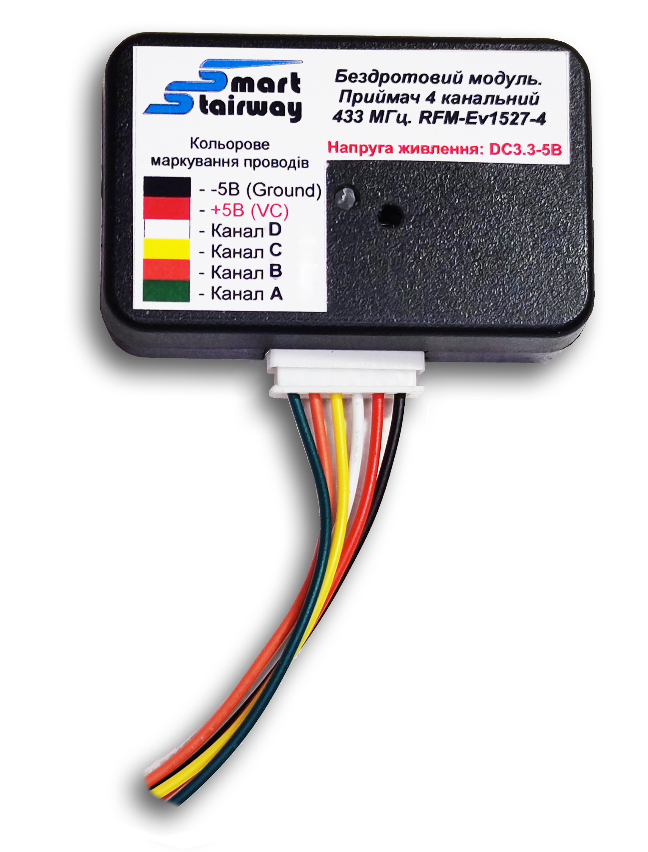 In addition to sensors and buttons, a receiver is also required. The receiving module has 4 channels. Channels "A" and "B" are designed to work with sensors, and channels "C" and "D" are for connecting buttons. The receiver comes pre-programmed for use with all equipment ordered with it. However, if you want to program your existing equipment compatible with the EV1527 protocol operating at 433 MHz (this could be radio remotes, buttons, sensors, etc.), the receiver allows storing up to 12 device codes. You can also program additional duplicate sensors and buttons, for example, if you need to increase coverage of intermediate zones or activate lighting from additional entrances.
The module has a plastic housing with a connector (3) for controller connection; a 6-pin connector with wires (4) is also included. The housing features an LED indicator (1) and a hole for a hidden programming button (2).

| Wire Color Coding | Connection to Controller Output |
| VC +5V | |
| GND - | |
| Channel "D" | |
| Channel "C" | |
| Channel "B" | |
| Channel "A" |
Below we describe how to program the module.
Programming the Module
- Clearing Memory. When clearing memory, all previously recorded codes will be deleted from the receiver. Only clear memory if you need to remove all device codes and re-program them. Using a thin probe made of dielectric material, press button (2) 8 times. Each press is signaled by a short flash of indicator (1). After the 8th press, the indicator will flash 7 times and turn off. Memory is cleared. No devices are paired with the receiver.
- Pairing Devices. For correct operation with the controller, "Mode #1" is used (channel activation upon signal from transmitter).
- Turn off all transmitters except the one you are pairing. Press and release button (2).
- Indicator (1) will turn on and stay lit until a sensor or button triggers.
- Trigger the device. After successful pairing, the indicator will turn off.
- Repeat the procedure for each subsequent device.
How do receiver channels work and why is it important to select the appropriate channel hardware?
The receiver has 4 channels. This means it can receive signals from 4 transmitters simultaneously and control 4 controller inputs.
For example:
- Channel "A" - the upper sensor is connected to the corresponding channel "A." Its activation will activate the receiver output connected to the controller terminal for connecting the upper pyroelectric sensor.
- Channel "B" - the lower sensor is connected to the corresponding channel "B." Its activation will activate the receiver output connected to the controller terminal for connecting the lower pyroelectric sensor.
- Channel "C" - the upper switch's radio button is connected to the corresponding channel "C." Its activation will activate the receiver output connected to the controller terminal for connecting the upper switch.
- Channel "D" - the lower switch's radio button is connected to the corresponding channel "D." Its activation will activate the receiver output connected to the controller's terminal for connecting the lower switch.
If you connect two sensors to channel "A," they will both activate channel "A" of the receiver. Therefore, if you want sensors and buttons to activate different receiver channels, you should use equipment with the corresponding channels. Please pay attention to this when ordering equipment. Up to 12 devices (transmitters) can be linked to one receiver.